Sunday, November 30, 2014

all engine mount bracketry complete

Over the last few days I duplicated all the DS brackets on the PS.  So now all the mounts are complete for now.  Sort of a milestone here! The work over the last few weeks has made this whole assembly incredibly stiff.  Here is the view of the bay with all subframes in there:

So that completes my list from July:

So I took a little while to think about where I ought to go next.  Pretty much, next I will be building the steering.  With that means the routing for the column, which brings the pedal position into things.  So I will be mounting up some interior bits and laying that stuff out next.

I tend to focus completely on tasks at hand, and don't let things like cleaning distract me.  The shop has become a mess.  I am not ashamed to show it off:


Cleaning it up is third on the new list, after close out shifter hole, and put dash frame back in.


Friday, November 28, 2014

Finished the DS connector bracket

Tapped:

 Here it is back in the car and bolted together:

Cap screws from outside the car: 

Welded on a gusset.

This bracket added a ton of stiffness.  To recap: there are a total of 3 brackets on the driver's side. 
1)  The main one.  attaches the subframe to the frame rail
2)  adds redundancy and some triangulation to the main one
3)  connects the engine subframe to the suspension subframe.

With just the main bracket in, I kicked the subframe and it visibly shook at a low frequency.  This was about cut in half with the addition of bracket #2.  After I finished #3, it is like kicking a wall

Next up is to repeat the last week's activity on the PS.

Sunday, November 23, 2014

DS subframe connection bracket

Amazon had these porter cable angle grinders for $30 so I grabbed one.  It is identical to my Craftsman one.  Which is to say it isn't very good.  Someone would make their million dollars if they made an angle grinder with a quick change arbor.


 I started the bracket that will tie the suspension subframe to the engine subframe.  Used the score and bend method from before:

 I lathed a couple rods to tap at 7/16 UNC and welded them on.  Then I shot the mating surfaces with weld through primer and tacked the bracket to the suspension subframe:
Next time I will drill out and tap the bracket, transfer the holes to the engine subframe, bolt up, weld the scored area, and make a gusset and weld it on.

Friday, November 21, 2014

DS subframe mount complete

Welded on the doubler.

Here is the underside where the new subframe tube mounts onto the frame rail doubler. These are my first upside down welds.  The technique seemed to be: dwell for a short moment on the 16ga frame rail, then drag the pool onto the 3/16 and dwell longer.  I did a series of spot welds without letting the weld totally cool before advancing.  The last thing I need is for the puddle to fall out leaving a humongous rip in the frame rail.

Here you can see the piece that plugs the hole, and the tube welded on.  A Gusset will be added to the back so that all the force in the tube isn't getting resolved into a piece of 1/8 sheet only.

If I sit on the bumper and kick the subframe it is probably at least 4x as stiff front to back now.  It is really hard for me to estimate what crash loads would be like on any of this stuff, and I haven't found how to design for it in any of the books I have been reading. Fortunately there are 3 more brackets to make for a total of 7 tying the engine into the car.  I am really trying to push for overkill on this to protect myself from my ignorance.

Thursday, November 20, 2014

Bracket final fab before install

Continued pushing on with the doubler today.  Welded on the rods today, then brought the holes up to tap size and tapped them:

Tapped holes:

My biggest drill wasn't enough to make big enough holes for the rods to go it.  I had to use the plasma to enlarge the holes a bit:

Here you can maybe finally see what I am up to if you had trouble picturing it.  The bracket will fit up onto the frame rail.  The tube will Connect to the bottom of the bracket, and go down and to the left and meet up with the subframe.


Wednesday, November 19, 2014

Lining up the DS subframe reinforcing bracket

Trying to hold all the pieces in place that need holes and need welded takes way more hands than I have.  Also, I don't like clamps for that sort of job.  First I drilled the holes in the flange at a small size.

 I transferred the holes to the doubler at the small size.  Then I tacked the two together (below).  I figured out that tacks I want to separate later I should ignore the settings for the welder, and use a very insufficient voltage.  That way the wimpy welds are easy to cut later.

Not shown are the rods I turned.  If I just tapped the doubler I would get about a thread and a half holding the bracket on.  So I used the rods to double the doubler.  Tripler?  Anyway.  Shot it all with weld through primer and will pick it up next time.

Heater is kicking butt BTW.  Warmed the shop to a balmy 47° from 33° in about 35 minutes then ran at less than 50% duty cycle to maintain it.

Tuesday, November 18, 2014

Lowes

Tonight I stopped into Lowes to snag a couple cap screws to hold in the bracket I am welding up.  Oddly, at the register the cashier told me she wouldn't sell them to me since the bar code was rubbed off.  She tried once to type them into the system and didn't find anything.  Then she offered to call hardware.  When I said please, she said they wouldn't be able to help.  No offer to get someone, to help me.  Just sent me away.  I started to go back there to look for some screws with an in tact bar code, but then I got ticked at the disrespectful and lazy way I was handled and flung them into a display and left.

I wish there was some sort of card they could give people who spend like $5000 per year in their store that you could show them so they would make a little bit of effort.  Not the first time the Hatfield store on 40 ft Road has jerked me around.  It will be the last.

Sorry to bug you all with this, but I think it comes with the territory of parts and tools bought and endorsed in pursuit of the build.  Especially since the post just below this one has >$100 worth of stuff bought at either Lowes or HD in the last 5 days.

Saturday, November 15, 2014

Here, take this extra pair of gloves, my hands are starting to get a little sweaty.

I went out in the garage on Friday and it was 40°.  I went right back inside.  I hate to work when it gets that cold.  I resist stooping down because I hate how cold my clothes feel.  My hands don't work right, I fog up my face shield.  Fortunately, last weekend I ordered a 5000 watt commercial forced air heater for the garage.  I chose electric over kerosene or propane for a few reasons:

1) I don't like messing with carbon monoxide, especially if I forget about it and it runs a long time
2) I want to be able to leave it unattended and not always be thinking about what is near it.
3) I don't want to keep all that fuel in the garage
4) I don't want to keep all that fuel outside
5) I don't want nasty films, odors, or soot deposited on things
6) I don't want to worry about running out of fuel, or having to remember to go get more.
7) I already have 240V power in the garage

Anyway, I got the Stelpro RUH5 from Amazon.

It has a thermostat that switches the full 240V  I ran 3/4 EMT tubing down and put the thermostat just inside the door, so I can reach out and crank it on a while before I go out.  

I was worried about whether it would be enough power.  It seems to be; Tonight it raised the temperature from 40° to 48° in maybe 30 minutes.  I will seal some gaps out there to help efficiency.

 After I finished installing the heater I started cutting metal for the extra subframe mounts.  Had to add a block to get a shallow enough angle:

 I am getting better at drafting brackets onto square tube then cutting them out:

Wednesday, November 12, 2014

tube angles

The tubes go 45° across a cube, and one of them gets cut on the horizontal plane, the other on a vertical plane.  The miter isn't clear to me for that.  It is also not clear how many degrees apart they should be.  A quick Solidworks construction:
35.26° miter


Clocked exactly 60° degrees.

Worked out well:


diameter * Pi /6 gave me the arc length for 60° which I put on a note card and wrapped. 

I used a piece of angle to transfer clocking marks from one end to the other:

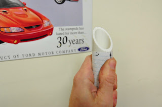
Anyway it is wicked easy to get confused with this which is why I like to work in PVC first; Which way do I clock 60°?  Also do I want 35.26°, or do I want the compliment of that when I set the miter saw?

Nothing makes me feel dumber than trying to cut crown molding with no chart, and this is sort of like that.  There are lots of weird things like this that I think comes from us constantly trying to break down 3D things into 2D ideas.  Like out of the three perpendicular planes why is there one horizontal plane (top) and 2 vertical (front and right).  maybe horizontal and vertical are inherently bad language to describe 3D.  I think it was Wittgenstein that wrote about how the language we create and understand limits the ideas we can have and how we can communicate.  Maybe this is why things like cross products and angular acceleration seem so weird to us (we live with 2D language and ideas).  Or maybe two eyes is the wrong number to fully take in a 3D world.  Maybe depth perception is not really the same thing as seeing 3D which we couldn't even comprehend.

Tuesday, November 11, 2014

front subframe strength and stiffen part 1


I attached the front subframe and tightened it down and it wasn't that stiff.  I don't want to count on the transmount and the bell housing to stop the engine from moving, and I want the steering rack mounts to be very stiff.  Also, 4 very large bolts held in the subframe in the mustang.
Top of the image shows the area to be worked on.  The hole is the attachment point.  You can see the spring perch near the hole

Decided to add a 3/16 doubler.  Since things were a little curved in the subframe I bent the double both ways with the press.  Shot things with a little weld through primer.  I also cut out the extra spring perch which will be in the way later.


BTW weld through primer really is weld through primer when the voltage is cranked up for thicker material.  No stubbing this time.  Zap:

 I filled in the hole in the frame, which is exactly where I want the tube to go.  I am waiting to weld it so that I can tilt it a little if I have to.  I also started trimming a piece of PVC as a template for the tubing.

Also, I was really close to running out of .030 wire.  11 lbs should hold me for a while.  Order from Amazon, comes from Grainger.  Payed less than on Grainger's site.

Thursday, November 6, 2014

Shifter hole blank

I am down to number 4 from the other day.  I was up too late last night, so I only spent 45 minutes out there today.  Just enough time to cut the blank to close out the shifter hole.  Bent it with my hand in the bench vice.  A little more cutting and grinding and I should have a really good fit:


Wednesday, November 5, 2014

plug welding

I took care of a few things tonight.  One of them was to weld up some burn throughs.  To plug weld you need to back up the hole with a piece of copper, otherwise your attempt to plug the hole will create a bigger hole.  Here is the other key that I missed before, turn the heat way down or your copper will join the filler material.  Many places sell what are called copper spoons for plug welding.  Eastwood's is like $40.  For free you can smash an old piece of pipe in a vice:

Plug weld visible just above the clamp at the opening:

Tuesday, November 4, 2014

Gage pins

Made another craigslist run tonight.  Got some gage pins for pennies on the dollar.  I have wanted a set of these for a while.  I am glad to not have to use my $15 Harbor Freight transfer punches as gage pins anymore which is only slightly better than using your fingers.

Monday, November 3, 2014

Tunnel details

I had about an hour this evening and nearly felt overwhelmed by all the details that need to be completed before I can call the tunnel done:
1) Grind the underside of the tunnel
2) Cut steel and weld in the gaps on top
3) Plug all the burn throughs
4) Close out the stick shift hole
4) Seam sealer everything
5) Primer

Only thing to do is just start working.  I finished number 1 and 2/3 of number 2.

Here is the passenger side of the tunnel as it is right now

 Close up of the driver's side.

Underside.  It has come a long way since I tried to simply slam it wide enough with a hammer.

Sunday, November 2, 2014

Tunnel tack

I tacked in the tunnel today.  I have been curious about welding photography and decided to go for a selfie.  I didn't have the courage to expose the arc:


Once I got everything tacked there were still a couple gaps up to about .080.  I went to the underside of the car and closed the gaps with a couple of light slams with the BFH.

Saturday, November 1, 2014

tunnel prep

After a few more rounds of grind and check I am getting pretty close.  Score and fold for the tunnel works nice.  I ground all the sealer and paint off the floor where my welds will go.


Decided to take the engine out for better access to everything:


I forgot how messy the place gets when everything is out of the car.

Here I am closing up the end of the old exhaust tunnel tubes.  The one on the right is done.  Just trying to keep moisture out mostly.

For whatever reason, both sides of my new tunnel met up poorly with the floor.  I welded on some extensions.  Other side is fully welded to keep out moisture and provide strength.  This side is tacked for now.