Sunday, June 22, 2014

Plasma FTW

I got a full day out there in today.  I sort of needed it as this subframe business was getting nowhere with 1-2 hours per day.

I layed out the Focus subframe and the Mustang subframe and drew a line for what needed to come off initially so that I could get everything together and start laying things out.  I started into it with a cutting disc.  I was put off by the weird angles and cuts that would have to meet up, and by the mess I was about to make.

I dragged the subframe next door and asked my neighbor if I could use his plasma cutter.  Holy smoke I couldn't believe how much easier that was.  What would have taken me an hour and a half was done in literally 5 minutes.  I am really rethinking about getting one of these now.  I still have all the chassis work to do on the back end of the car, and Eastwood is having a sale on theirs right now.  Only downside is that with a cutting disc you have time to contemplate on something dumb you are about to do.  With the plasma it is already done.


Plan for the second half of the day in red.  Green is the subframe position from hard points on the car.

Step 7.

Step 9.


Thursday, June 19, 2014

Subframe trimming

Had to cut the subframe to fit between the frame rails:
Was:
is:

Spring perch x section:

I am always amazed at what an angle grinder can do.  They are really cheap, can go through the thickness of this 10ga steel in less than 4 seconds, accurate enough to slice off a paper thin piece of steel, and can debur this whole part as quickly as you can move it.


When I slid this up into place I noticed a few things.  The rack mounts are actually not supposed to be centered in the car.  Also note in the above images how unsymmetric the engine mount bosses are relative to the symmetry of the cross member.  I am not sure yet why that is but I have a theory to check out tomorrow.


Sunday, June 15, 2014

Subframe the easy(?) way

I made it to the Pypes car show this weekend. It seemed a bit bigger than the other years I have gone.  There was a beautiful white Mach 1 fastback with a 460 and flat black side pipes peeking out that was just incredible.  It is one of those where you see it and just think, "if I could just have that, then my car itch is completely scratched for good."  no camera :-(

I was looking at the engine mounts in all the cars.  I am again not liking the little 1.25 tubing that I am trying to sneak through that tiny space to hold my engine.  Everything at the show had very stout mounts.  I started thinking about some alternatives.  I was wondering how the mustang subframe dodged the rack so I took a look.  Then started thinking I should just modify and use that...
The engine mount has a pass through for the rack.

Yeah, I will just have that, and amortize the mustang expense over some more harvested parts: 

Briefly contemplated leaving the control arms on and just using the mustang suspension.
The good:
track width is right
better brakes
no bump steer
ackerman
The bad:
shock towers are off by about 4 inches per side
Height is wrong
Wheels not in the right spot for forward/aft

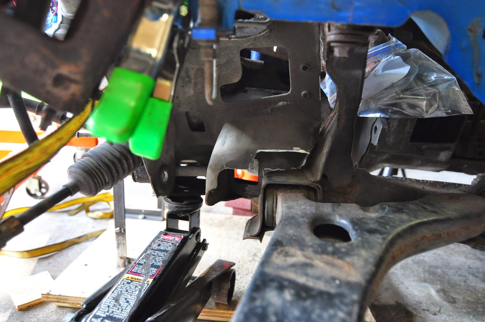
Here is a view with the subframe up under the car.  I think I will nibble a bit off the spring perch to let it pass inside the rails.   Maybe I can make some brackets to mate with the rails and then hold the frame.
 

Saturday, June 7, 2014

Falling into place

I chopped out more tunnel.  The engine came up another inch.  The original headers now clear everything.  There will be a lot less trouble dealing with bump steer and the ground clearance is now over 5 inches.  Both the suspension frame bits and the engine frame bits will be lighter, stiffer and stronger.  I'm glad I saw this problem through before moving on.  I feel confident now that I haven't left harder problems for later that could set me back.


was:


is:


I was worried about loosing the tunnel structure a while back.  Especially since it seems to have stiffening sections on the top of it.  I want to point out the two huge oval holes through the fire wall next to the tunnel (steering column and heater core).  Also note that they have no doublers.  Sort of adds to my suspicion that this is ok to do.
Flanges clear!  

I know it's rookie to buy and return two sets of headers and go out daily to chop a little more and a little more of the tunnel.  I am a little afraid to look back and see when I started this step of the build.  I am learning a lot as I go through this, and I am trying to pass on what I learn, especially if it is stuff that I don't find from reading other build threads, books, or forums.  

I want to pause and mention that I am grateful for the ideas, guidance, tools, and help that so many of you have offered up.


Friday, June 6, 2014

new headers -> old headers

New headers from summit!  I feel like such a redneck whenever I get psyched about things coming from Summit.  Option 3 the block huggers:


Shortest lived excitement ever:
Yep there is a reason why all the links and threads about block huggers link to hotrods...

I assumed it was because hotrods have narrow frame rails.  Turns out...

There is no way they will work with rack and pinion steering.  Well almost no way.  Maybe if I buy a front sump pan, and go back to rear steer. So we will say no reasonable way.  I read in a book that worm and sector steering will feel identical to rack and pinion if it is stiff enough.  Which is like saying a port-o-john would make a good home if it was just bigger, not plastic, had furniture, and smelled a little nicer.

Those of you keeping score know that I have three non ideal options:

1) Original Shorties
+ Free
- DS collector is in the way of the subframe

2) Tri-Y
+ Look cool
+ DS fits with no modificatin
- Limits how high the engine can mount
- PS collides with the subframe

3)  Block Huggers
+ nowhere near the subframes
+ great flexibility for routing after the header
- Hits the rack
- Hits the starter
- Hits the engine mount
-BTW you get what you pay for.  Mounting flange is about .060inch out of flat.

Looks like it will be shorties.  Today I loaded the DS one back on.  Now that the engine is an inch higher, it barely interferes.  Since I would like to go up another inch for bump steer, They may clear with no modifications to anything.  Difference now is that back when I started this saga, I was not planning on chopping the tranny tunnel.  We will see if it is as fun to send things back to summit as to get things from them.


Wednesday, June 4, 2014

preliminary engine frame layout

After getting the headers, engine mounts and rack into place, I found that the subframe and header interfere pretty badly on the passenger side.  That is sort of strike two for these headers since they also limit how high I can mount the engine.  I ordered some block huggers last night.  We will see if they fit any better.

I had a plan to bring a tube under the engine and up to the other side (as shown in PVC in the last post).  That tube would hold the rack and both engine mounts.  Rather than one bent piece that would have to be bent very accurately I had a plan to weld up as shown below:
Proposed frame design.  Uses 1.125, .083 wall tube as a starting point.  The ears on the horizontal piece would hold the steering rack.

I am concerned that having the rack tied so indirectly to the suspension mounts could lead to relative movement between the two.  I made a quick FEA model to see if that was a valid concern. The cross piece below represents the engine.  It is essentially rigid.  The plot is displacement in inches.  Please note that the distortion is greatly exagerated in this plot.

There are two loads applied:
1) Lateral 2 G load.  I know we can only corner at about 1G, but wanted to account a bit for transients, and bumps that are unknown. Assume 450/32.2*32.2*2 = 900lbf lateral

2) Torque.  Torque is not what you might think it will be.  It is being reacted against the Diff, which means you get multiplication from the transmission.  Some of it will be resolved by the transmission mount, but because its footprint is so narrow it won't take that much.  Let's assume the engine mounts take it all.  Assuming max of 400 ft*lbf  and 3.5 multiplication in 1st gear we have 16800 in*lbf.

3) Axial and vertical load not considered.  The vertical loads are well resolved in this configuration.  The axial load from braking and accelerating would not be carried by this frame.

Already we see that this is an unacceptable amount of movement for the rack.  I don't know what acceptable looks like except that .125 inch won't be it.  Movement of the rack will make the car handling unpredictable.

Even with that information there is something to be gotten from the stress plot:
I am not that worried about the yielding shown.  I didn't pick cromoly for the model, I didn't model actual mounts, and I didn't include other stiffening members that will be present.  Observe the not surprising result that everything below the engine has no stress.  The engine is so much more rigid than the tube that all load passes through the block if the engine mount is stiff enough.  If I use rigid engine mounts, then it may be possible to triangulate from the rails to the mounts, and not bother with passing under the engine.  The under the engine piece can tie into the subframes more directly.  If I use rubber engine mounts, then this assumption may not be smart.


Sunday, June 1, 2014

placing and jigging major items

Now that I have the hole cut for the transmission cut, I figured I should put the bell housing and engine back in just as a double check.  It is a good thing I did.  I had been torqueing the engine to the side with a weight and later with a jack to make the top face of the shifter housing parallel to the transmission tunnel.  This seemed reasonable.  Turns out it isn't right.  The top face of the shifter is 4° off level if the engine is level on the roll axis.  Which meant the transmission at its new orientation collides with the Passenger side too.  Some quick (and hopefully final) chopping:


Notice in the top picture I elected to make a cut and slam things a little wider rather than remove a bunch more material.  So now it is tempting to get some steel and close up this hole I made.  I know things will shift around a little, and that I may have to adjust position when everything gets to its final place up front, so I decided to make the subframe and engine mounts next.

The first step here is to see where everything lands.  I took the rack from the mustang and need to place it in the focus.  I Recall from my calculations that not relocating the steering arm means that I want the rack as far forward as possible to get close to neutral ackerman, I also know that I will want it as high as possible to make the battle against bumpsteer more manageable.  So now lets locate it there.  The mounts are about 1.25 inch diameter with the bushing removed.  PVC is 1 3/8 inch O.D.  So I cut a short length and turned it down in the lathe until it just fit.  Jammed it in there and pressed the other end into a piece of wood:

By clamping the wood it is easy to tweak the rack to the right angle and height I want while I design the frame.  Next I will need the other important pieces in there.  So I remounted the headers and the solid stamped piece of the engine mounts.  Then I cut some more PVC and started to look at where the first piece of engine cradle will run to:

Hold the rack, but miss the steering column
Reach the engine mounts
Miss the headers
Bolt onto the suspension subframe.


Doesn't fit perfect yet, but getting there:

Also went to a car show in Skippack today.  Some nice cars there:


And just in case you think I only take pictures of British cars:

I suspect this belongs to the family I bought my donor car from.