Thursday, November 5, 2015

rear suspension planning

So there are 3 practical choices for my rear suspension

View from above looking down.


1) Triangulated 4 link
This is what they use on the mustang from the factory.  Two lower trailing arms mount to the axle out near the wheel and slope toward the middle of the car.  Two upper control arms mount near the differential and slop towards the outside of the car:
Advantages
Since the arms are angled they can carry lateral loads for the car, so you don't need any other links. Also, If this works as is, then I avoid welding brackets on the axle, and avoid making control arms ($$). 

Disadvantages
Design math is more complicated.  The links are more highly loaded than in other designs. The criss-crossing arms take up a lot of space under the car.

2) Four link with parallel lower link, triangulated uppers
You wouldn't think this changes much, but it is significantly different.  
Advantages
This shoots the arms outside the frame rails into the space where the focus trailing arms mounted before.  Pretty handy. 

Disadvantages
Now the upper links carry all the lateral load.  

To ensure we have roll understeer, we must have the lower trailing arms sloping down toward the front of the car, which likely puts the mounts below the scrub line.  This also puts the roll center really low, which will decrease the roll stiffness of the chassis.
 
Also, I will have to remove the brackets which currently hold the lower links and weld on brackets that are pointed the needed direction.

3) Parallel four link plus panhard bar
All links are parallel to the travel direction.  A lateral link positions the axle (shown in pink above)
Advantages
This is how solid axle rear suspension for a project like this is often done.  Easiest to tune and adjust later.  Simple design.

Disadvantages
Car has different roll center for left turns and right turns.  Using a watt's link instead fixes this, but significantly complicates things.
 
The panhard involves the maximum amount of welding and fabrication compared to the options above.  It also requires making all the links and buying up to 10 heim joins at ~$50 each.

There are, of course many other suspension choices.  I don't want to get into why I didn't choose them, and who knows I may choose one after exhausting my look at these.

I put the axle in place and at ride height to see where things lay with the mustang trailing arms.
This is really encouraging. The jack is holding the original lower link at level.  It lands a comfortable distance below the frame rail, which may make bracket fabrication easy, light and strong.  The other encouraging bit is that there is about 4 inches clearance to the frame rail in the bump direction.  I may be able to avoid notching the rail all together.  I would like to have 4-5 inches of travel in both the bump and droop directions.


Wednesday, October 14, 2015

garage engineering

I rearranged some stuff to get the bikes out of the way.  I went through my two disassembled cars and made some easy decisions about some parts I won't need and have no resale value.  I sold my car ramps, and my catalytic converter, and my mustang (if one could still call it that).  The guys who came to get it were super cool.  Here it is waiting for it's new owner...


I made some accommodations to make room for the Tig welder.  Weelded some horns onto my rack to hold hoses:


 Printed this little mig caddy to hold brushes, tips, slips and a can to hold the wire clippings.  (took 17 hours to print!)
 
Welded on a bracket to hold the angle grinders:
 
Looking better:


Welded a piece of old conduit into a tube and to a piece of bar to bolt under my bench and get the craft paper out of the way:
 
 
Room to work again...  Once I grade the midterms...

Saturday, September 19, 2015

rear suspension overview

So I have been reading about rear suspension design in a few books.  To begin, the job of any rear suspension is to:
1)  Prevent the wheels from moving left/right or forward/backward relative to the body.
2)  Allow the wheels to move up and down together (bump)
3)  Allow the wheels to move up down independently of each other (roll)
4)  Minimize weight

Since my plan was to build this car from the mustang donor, I committed to a solid axle rear end as opposed to independent rear suspension.  I think many people poopoo solid rear suspensions.  It isn't really that bad:

1) If the road is smooth, they don't really work worse than IRS.
2) They are cheap.
3) You don't ahve to worry about camber changing, toe changes, and scrub.

As I alluded to previously there is a balance to be had between slapping something together, and making something that works well.  Here are a few ways that attention to the design can help:

Roll steer
When the car body rolls in a turn one wheel may move back more than the other or one moves back and one moves forward.  This changes the direction that the rear of the car is going. 

 
Top:  No roll steer.  Axle pointed in same direction as the body.  The line from each wheel intersects the line from the axle indication instant center.  This is the point that all four wheels are turning about.
 
Middle: Roll understeer.  The outside wheel moves further forward than the inside wheel when the car body rolls.  Although this appears to move the rear of the car into a tighter turn, it actuall moves the instant center out, and makes the car turn on a larger circle.  This is stable.  Also, note how this took our perfect steering ackerman and turned it into pro ackerman.
 
Bottom:  Roll oversteer.  The inside wheel is moves further forward than the outside wheel.  This tightened up out turning radius.  This is unstable.  The car roll made the car turned tighter, which will make the car body roll more, which will make the car turn tighter still, which mill make the body roll more... until you spin.  Note that this also creates anti ackerman.
 
It is not the goal to make a design that has no roll steer for the entire range of suspension travel and roll.  I don't even know if it is possible, but if you could you would almost certainly have terrible handling as you abandoned all other design goals.  The goal should be to keep roll steer to a minimum, and to sacrifice whatever is needed to be sure we have roll understeer.
 
Antidive and antilift
If side view instant center for the rear suspension is in line center of gravity then the thrusting force from the wheels will be applied directly to the CG and the car will not squat when accelerating.  The flatter the swing arm angle relative to the ground, the larger the moment created by the thrusting wheel force compared to the CG, and the harder the car will squat.  Fine for a drag race.  You generally want a little squat, and a little dive on braking so that the driver can feel what is going on.


Top:  100% anti squat
Bottom:  0% anti squat.  Amount of squat depends on spring rate.
 
Roll center
If we imagine being aft looking forward.  We can imagine that there is a point that the car will roll about.

Left:  Roll center below the ground.  Notice body moves about roll center
Center:  Roll center at axle height
Right.  Roll center near CG.
It should be noted that the body will not roll on the paths shown.  As soon as the body rolls a small increment, the suspension geometry changes  and the location of the roll center changes as well.

The centrifugal force is acting at the car's CG.  So the lower the roll center is greater the body roll will be in a turn .  Cars counteract the body roll with sway bars, which essentially increase the roll stiffness without raising the bump stiffness.

A higher roll center will cause an increased jacking affect.  In other words, the more the body leans, the higher it will get.  High roll centers also cause camber to change significantly in roll (although we don't care about this with a solid rear axle!)

Saturday, September 12, 2015

cobwebs and crickets

A little over 2 months since the last post.  Embarrassing.  The main reason for this is that we got some attached bicycles to ride around with the kids.  They are too big and heavy to disconnect from our bikes and take to the basement after each use, so guess what: they all now live in the last open space in the garage.  They make it completely impossible to open any drawers on 4 of 6 tool boxes, impossible to use the lathe, press, or workbench, and they use up the last spot of floor space where I could work.  Epic.

As if that wasn't bad enough spacewise, the mustang has finished shedding parts into my garage, and then I got this beauty off CL which is taking up some space I didn't even have:

At this point only the fact that I have a clear goal is separating my garage from that of a hoarder's.

Also school started 2 weeks back and I am teaching a new course in the afternoons.  However, my luck is turning.  The course I am teaching is a subject I know really well so it hasn't destroyed my free time. 

I also finally bought this:
 
I wish I had gotten it much sooner.  I am starting into the rear suspension design which would have been impossible without this book.  I say this already having 4 books on the subject.  One of the suspension chapters begins with an awesome quote:
 
"Figuring the suspension of a car is almost entirely a matter of making useful approximations.  It is not an exact science.  But neither is it a blind application of rule of thumb principles."
 - Maurice Olley 1961

I think we all tend to think that someone who analyzes less than us is a maniac, and someone who analyzes more than we would is too academic for the real world.  It is hard to know how much is the right amount.  I think this quote sort of helps ground that effort.  It makes me think I am doing things about right actually.  Although perhaps no matter what one's level of care were, it may make him think that!

I hope to be posting again soon with some rear supsension discussion!

Sunday, June 28, 2015

making room for the axle

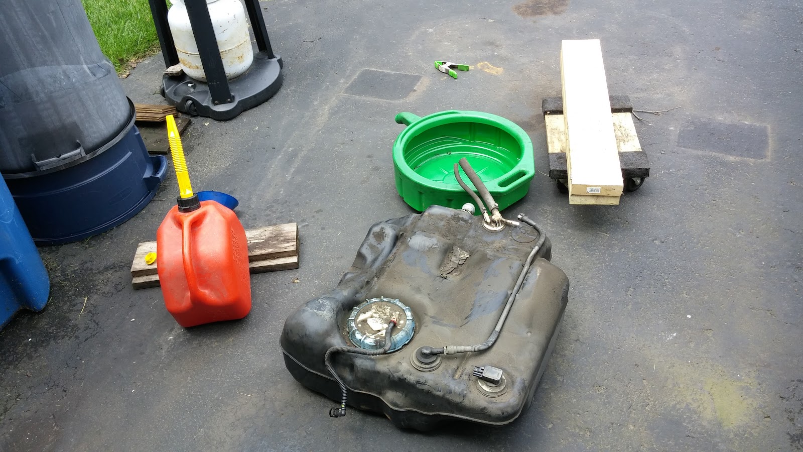
Pulled out my gas tank with 2 year old gas in it.  Drained some, filtered it and ran it in the lawn mower.  Seemed to run fine.  Put some in my wife's car and the rest fit in gas cans.  Glad I didn't have to pour it over the heads of baby bunnies or anything like that.
 
So I put the axle under the car and slid the wheels on.  The spare tire well is in the way as you can see here where the axle is still too low:
 
Here is the last unmolested area of my car:
 
 Lested:
 
 
I wrote down the fender gap before starting this project; 3 inches.  Here is the wheels now at 3.5 inches:
 
Not very visible from the back which is good.  I think not using a bright shiny diff cover helps with this.


Saturday, June 27, 2015

focus rear subframe out

back from vacation.  Pulled out the focus rear subframe today.  It was pretty hard to get out for just 6 bolts, two shocks, 2 ebrake cables, and 2 brake hoses:


 Here was a nice surprise:  
this is the Mustang brake drum inside the focus wheel... same bolt pattern I think.  Which means I won't have to redrill the hubs.  If this is right, it may be the first thing that hasn't been the hardest it could be.  The studs are larger for the mustang, so I may need to do something creative there.

I pulled out the exhaust and the rest of the heat shielding.  Will get some shots under the car once the fuel tank is out.

Monday, June 15, 2015

V8 no wheel drive

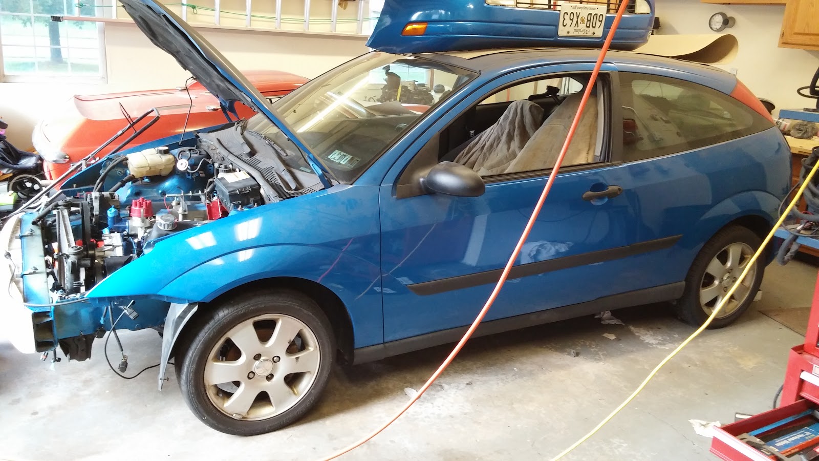
Here it is. Ready to go nowhere.
 

Time to get started on the back end.  I put the mustang on some harborfreight furniture dollies.  This was not the best move.  When I was rolling the car around later one of the casters exploded and left the car stranded in the middle of the driveway.  I still need a better way to move a wheel-less car around.
 
6 bolts, two ebrake cables, and a brake hose later:  Axle out.