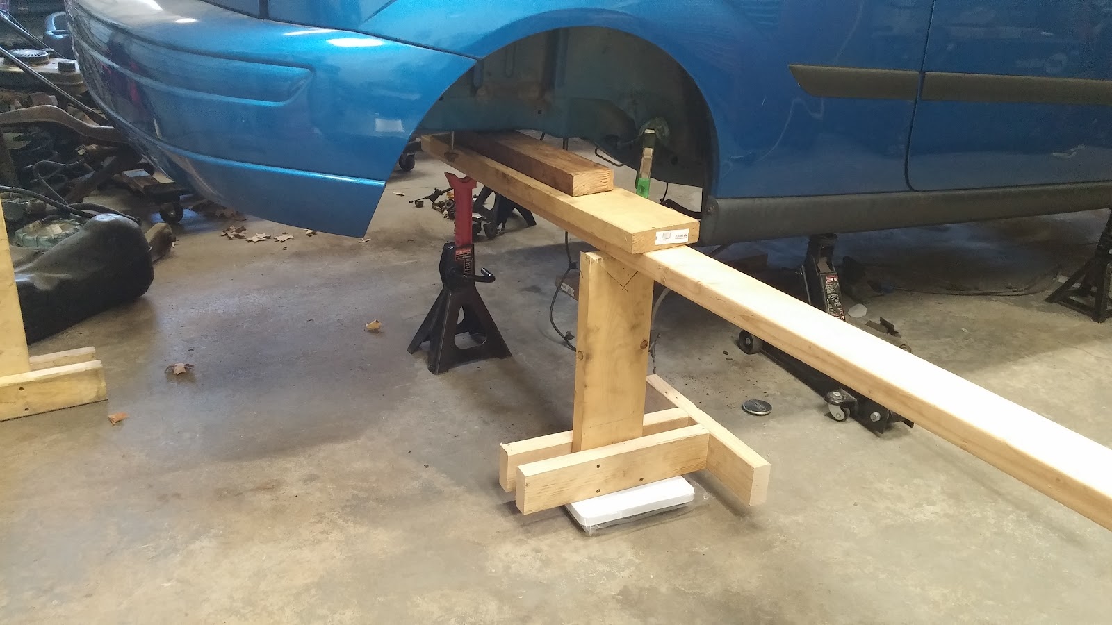
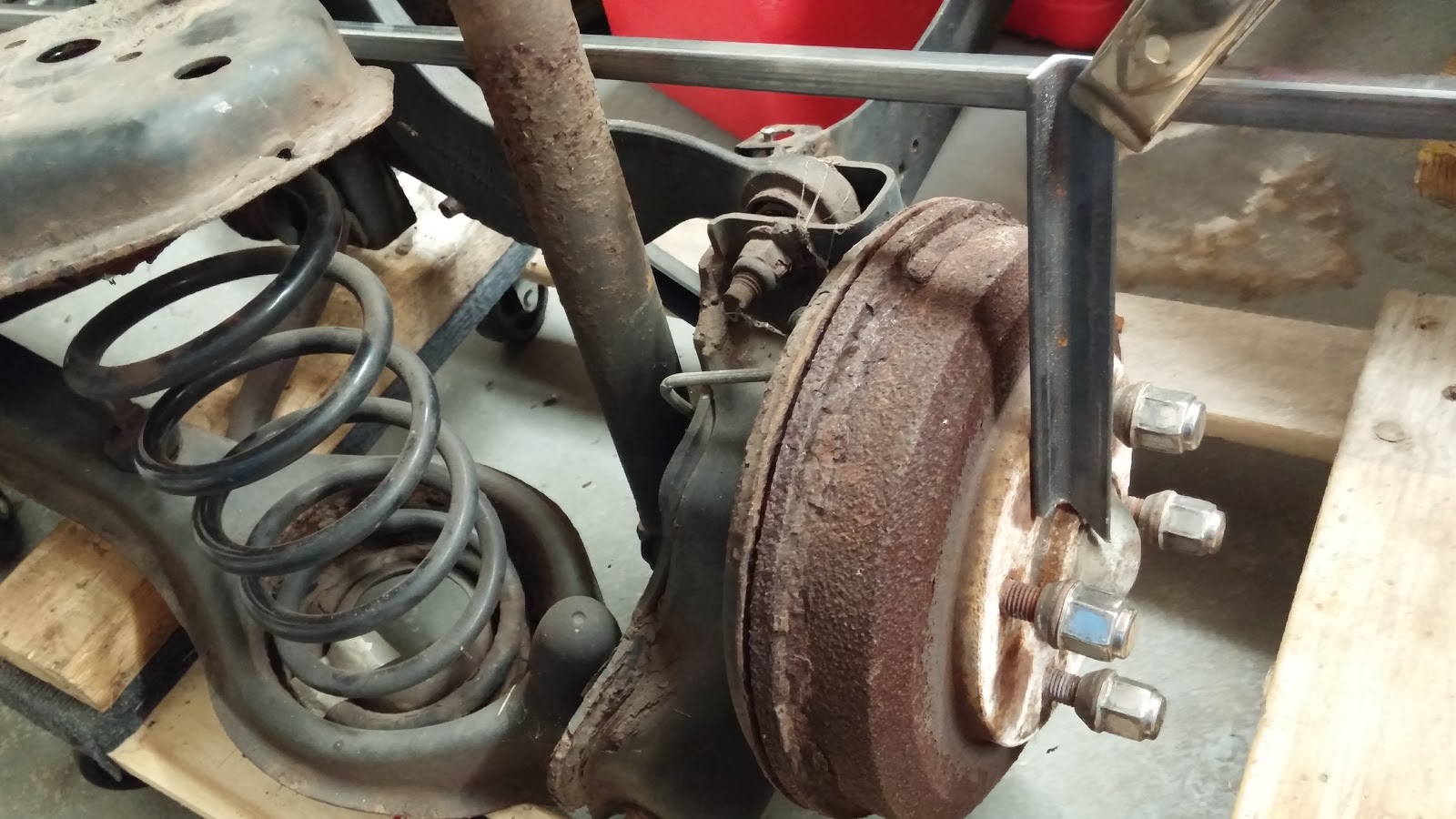
For now I will keep these so they can be removed. That way I can tack the brackets to hold the axle in exactly the right spot, then pull the brackets off the car and weld them properly. Later I will add holes to plug weld these on permanently. 1/2 inch grade 8 bolts + weld may be overkill. But this is one of those things that is absolutely not allowed to break. Looking at the stock control arms and the connection at the axle makes me feel good that I won't have any problems.
Thursday, January 28, 2016
Thursday, January 7, 2016
suspension bracket
Finished welding up the PS bracket to hold the rear suspension. This bracket is critical to safety. If it fails then I would instantly lose control of the car. To attach it, I will bolt through the frame rail in 3 places, weld the forward and aft edges, and rosette weld it in a number of extra places.
Here is the bracket with the bolts:
I like the air drills for drilling on cars. They have enough power to get it done, and they are light and cheap. Feels real solid so far.
Monday, December 21, 2015
control arm brackets part 1
Started on the control arm brackets. I made a stand to hold the axle at ride height and in the right place. I hacked up some 3/16 box to wrap the frame rail.
Here are the first two pieces of steel:
The frame rails aren't perfect 90° angles so I used my bracket stretching trick from the front rails:
Close up passenger outside after stretching:
Passenger inside pieces after stretching:
After tacking together with the mig I went prime time and did my first welds that will matter with the tig. I am happy with them. Most of my practice was with .062 thick material. This 3/16 was easier to weld. I also have some new electrodes that seem to make the arc easier to control. I did these at 160 amps, which felt a little low.
Here are the first two pieces of steel:
The frame rails aren't perfect 90° angles so I used my bracket stretching trick from the front rails:
Close up passenger outside after stretching:
Passenger inside pieces after stretching:
After tacking together with the mig I went prime time and did my first welds that will matter with the tig. I am happy with them. Most of my practice was with .062 thick material. This 3/16 was easier to weld. I also have some new electrodes that seem to make the arc easier to control. I did these at 160 amps, which felt a little low.
Friday, November 27, 2015
rear wheel fitment II
I got the studs and spacers from summit. The studs are just barely too long to get behind the hub and use the regular draw them in with lug nut method. So axle out:
Diff cover off. Remove the axle pin retaining bolt:
Axles out and press in the new studs. It takes some attention for them to go in straight enough to not cause problems:
axles back in. new spacers
After:


The wheels go on easily now and can be bolted down. They are right out flush with the edge of the wheel well. If they bump far enough they will probably rub, but for now, I think they are in the right spot. If needed I can always face off the spacer a little in the lathe.
Diff cover off. Remove the axle pin retaining bolt:
Axles out and press in the new studs. It takes some attention for them to go in straight enough to not cause problems:
axles back in. new spacers
After:


The wheels go on easily now and can be bolted down. They are right out flush with the edge of the wheel well. If they bump far enough they will probably rub, but for now, I think they are in the right spot. If needed I can always face off the spacer a little in the lathe.
Friday, November 20, 2015
rear springs part 2
I spent some more time looking at spring and shock selection. As the suspension moves up and down, the angle of the spring changes if it is anything other than straight up and down. I was curious how much spring rate is lost from this travel, as well as how much extra travel length is gained. It is easy to work out:
From there I made a spreadsheet to evaluate real shocks. It turns out for anything much beyond 20° initial angle the spring rate falls very quickly for even modest displacement. I take from this that shocks are inclined to simplify installation, not to gain travel. That said, I do need to angle them. The top area needs to be inside the frame rails (not enough room between rail and tire to be outside, not enough height to be under the rail). If I mount them vertically that far inboard, then there will be too little roll stiffness, and too little roll damping. So I will need to incline them.
I saw a few inexpensive options:
Jegs double adjustable coil overs (currently $186 each) 6.5 inch travel
QA1 Promastar single adjustable (currently $163 each) 6.25 inch travel
QA1 Aluma matic not adjustable (currently $135 each) 5.125 inches travel
I also wanted to look at how long is the shock is as the car sits (ride height). The adjustable shocks are significantly longer. To use a longer shock, I will need to encroach into the truck area and/or mount it lower on the axle which is a potential hazard. While long travel double adjustables would be cool, I just couldn't justify the extra time, expense and sacrifice to space. Most other builds I have found seem to go the same route.
Here is what the spring rate loss is over its full travel as a function of install angle which is TBD. So for example, If I install the shock at a 15° angle from vertical, The spring rate at full bump will be 15% lower than at full droop, and the total axle travel possible is 5.4 inches. This is not including the additional loss of spring rate from the initial angle which is ~ 7%.
From there I made a spreadsheet to evaluate real shocks. It turns out for anything much beyond 20° initial angle the spring rate falls very quickly for even modest displacement. I take from this that shocks are inclined to simplify installation, not to gain travel. That said, I do need to angle them. The top area needs to be inside the frame rails (not enough room between rail and tire to be outside, not enough height to be under the rail). If I mount them vertically that far inboard, then there will be too little roll stiffness, and too little roll damping. So I will need to incline them.
I saw a few inexpensive options:
Jegs double adjustable coil overs (currently $186 each) 6.5 inch travel
QA1 Promastar single adjustable (currently $163 each) 6.25 inch travel
QA1 Aluma matic not adjustable (currently $135 each) 5.125 inches travel
I also wanted to look at how long is the shock is as the car sits (ride height). The adjustable shocks are significantly longer. To use a longer shock, I will need to encroach into the truck area and/or mount it lower on the axle which is a potential hazard. While long travel double adjustables would be cool, I just couldn't justify the extra time, expense and sacrifice to space. Most other builds I have found seem to go the same route.
Here is what the spring rate loss is over its full travel as a function of install angle which is TBD. So for example, If I install the shock at a 15° angle from vertical, The spring rate at full bump will be 15% lower than at full droop, and the total axle travel possible is 5.4 inches. This is not including the additional loss of spring rate from the initial angle which is ~ 7%.
Sunday, November 15, 2015
rear springs part 1
I find surprisingly little about how to calculate spring rates when I read. I thought about it and realized a few things
The amount of droop you have depends entirely on spring rate. The sprung mass at the rear rests on the rear springs. It doesn't matter if you have coil overs that allow you to dial the ride height up and down. If you know your bump travel, then the load at full bump is determined already as well.
"Tune to win" recommended that for a beam axle car you want a minimum of 3 inches bump and 4 droop. If you look at the travel on most inexpensive shock absorbers, the extended to compressed height is significantly less that 7 inches. I conclude from this that the shocks will have to be run at an angle to the axle to get the needed travel as shown on this car:
I never knew why that was done before. This means that spring rate decreases the further you displace, which is the opposite of what you would ideally want.
I also thought about the ratio of sprung to unsprung weight. As you roll over a sudden bump the axle is accelerated upwards. If the body of the car is light or the spring rate is high, the acceleration of the car body upwards is high. I think there is a perception that this affects passenger comfort only. It affects performance as well as it means the cars pitch is constantly changing which affects the suspension geometry, and causes the wheel loads to change dramatically.
If the wheel load is changing dramatically, then the cornering force that can be supported by the rear wheels is suddenly disappearing and reappearing. We have all felt this when cornering in a empty Uhaul truck which has stiff springs.
All this is telling me that I need to have an idea of the sprung and unsprung weights of my car so that I can choose an appropriate travel, and spring rate. I don't want to spend a lot to know this so I bought two bathrooms scales for $8 each. I know a regular car weighs about 3200 lbs. If half that is on the rear, then I have to support about 1600 lbs with two scales that go to 300 lb each. This is easy to do with levers:
The amount of droop you have depends entirely on spring rate. The sprung mass at the rear rests on the rear springs. It doesn't matter if you have coil overs that allow you to dial the ride height up and down. If you know your bump travel, then the load at full bump is determined already as well.
"Tune to win" recommended that for a beam axle car you want a minimum of 3 inches bump and 4 droop. If you look at the travel on most inexpensive shock absorbers, the extended to compressed height is significantly less that 7 inches. I conclude from this that the shocks will have to be run at an angle to the axle to get the needed travel as shown on this car:
I never knew why that was done before. This means that spring rate decreases the further you displace, which is the opposite of what you would ideally want.
I also thought about the ratio of sprung to unsprung weight. As you roll over a sudden bump the axle is accelerated upwards. If the body of the car is light or the spring rate is high, the acceleration of the car body upwards is high. I think there is a perception that this affects passenger comfort only. It affects performance as well as it means the cars pitch is constantly changing which affects the suspension geometry, and causes the wheel loads to change dramatically.
If the wheel load is changing dramatically, then the cornering force that can be supported by the rear wheels is suddenly disappearing and reappearing. We have all felt this when cornering in a empty Uhaul truck which has stiff springs.
All this is telling me that I need to have an idea of the sprung and unsprung weights of my car so that I can choose an appropriate travel, and spring rate. I don't want to spend a lot to know this so I bought two bathrooms scales for $8 each. I know a regular car weighs about 3200 lbs. If half that is on the rear, then I have to support about 1600 lbs with two scales that go to 300 lb each. This is easy to do with levers:
Where Fs is the force on the scale. Fc is the weight of the car. Fj is the force on the jack stand
I put the first side as shown and saw that the car was off both jacks and that the load was much lower than I was expecting. So low that it would be below the scale limit if directly measured:
198 lbf! This seems impossibly light. Add a battery (35 lbf), A fuel cell and gas (75lbf), 20 lbf for all the brackets yet to be done. So about 330 lbs unsprung
Sprung mass:
200 lbf. Add wheels, tires and spacers (75 lbf). So 275 lbf total.
The shocks, springs, control arms, and drive shaft are partly sprung and partly unsprung. If we neglect these for a minute we have 605 lbf for the rear weight. I am concerned, but not surprised at how light the rear end is compared to the front, and concerned at how heavy the axle is compared to the car.
Saturday, November 7, 2015
Rear wheel fitment
I would like to use the stock focus wheels to save cost and maintain the sleeper design. There is an issue here though. The front hub that the wheel slips over is 2.485" diameter. The rear hub is 2.510". Initially I was excited that they are essentially the same, but the wheel that easily plops over the front hub, will not go over the rear.
Originally I noticed that the rear track width between the mustang and the focus was only about an inch different. Since track width is to the center of the contact patch this includes comparing different tire width and wheel back spacing.
I decided to measure the distance between the wheel mounting flanges to get a more objective comparison. I used some old metal stock to make a big caliper, then slid it off and measured the width on the original Focus suspension:
59.125" wide. I noticed that the suspension is at full droop. Accounting for this (control arm is 19" between the pivots and is 23° down from horizontal) puts the focus width at 62.125".
It was more straight forward to measure the mustang axle: 59.5". With the wheels on the axle, not quite fitting over the hub, they are out about .300 per side from seating against the brakes, so at 60.1 inches, they seem 2 inches narrower than stock, quite close to touching the inner wheel well:
So I have 3 options to get the wheel to fit over the hub:
1) Lathe the axle hub
I would only need to take about .010 off the diameter. This would mean removing the axles. I don't know if they would fit in my lathe. I am not wild about this option since this seems like I will end up too narrow
2) Grind out the inside of the wheel
Still concerned that the width will become too narrow for the wheels to clear the wheel well
3) Custom spacer
There are lots of ways this can be done. I think the easiest way is to buy a pair of aluminum spacers and press longer studs into the axle hub. This is cheaper than a wheel adapter, and saves me from the strength and vibration issues that come with that route.
The mustang studs are 1/2 -20 thread. The focus is M12-1.5. The mustang lugnuts do fit in the foocus wheels, so I don't HAVE to change them. It would be nice, so I looked at whether I can get any wheel studs that are long enough and will press into the flange. Just to make sure of the knurl diameter, I knocked one out and measured it:
Originally I noticed that the rear track width between the mustang and the focus was only about an inch different. Since track width is to the center of the contact patch this includes comparing different tire width and wheel back spacing.
I decided to measure the distance between the wheel mounting flanges to get a more objective comparison. I used some old metal stock to make a big caliper, then slid it off and measured the width on the original Focus suspension:
It was more straight forward to measure the mustang axle: 59.5". With the wheels on the axle, not quite fitting over the hub, they are out about .300 per side from seating against the brakes, so at 60.1 inches, they seem 2 inches narrower than stock, quite close to touching the inner wheel well:
So I have 3 options to get the wheel to fit over the hub:
1) Lathe the axle hub
I would only need to take about .010 off the diameter. This would mean removing the axles. I don't know if they would fit in my lathe. I am not wild about this option since this seems like I will end up too narrow
2) Grind out the inside of the wheel
Still concerned that the width will become too narrow for the wheels to clear the wheel well
3) Custom spacer
There are lots of ways this can be done. I think the easiest way is to buy a pair of aluminum spacers and press longer studs into the axle hub. This is cheaper than a wheel adapter, and saves me from the strength and vibration issues that come with that route.
The mustang studs are 1/2 -20 thread. The focus is M12-1.5. The mustang lugnuts do fit in the foocus wheels, so I don't HAVE to change them. It would be nice, so I looked at whether I can get any wheel studs that are long enough and will press into the flange. Just to make sure of the knurl diameter, I knocked one out and measured it:
.615 dia.
Nothing in M12 is even close to that big, so for now I will order long mustang studs. In the future, if I have the differential apart, I can remove the axles and have new smaller holes drilled 45° from the current ones. I don't want to do it by hand now, because with 3 inch long wheel studs and no hub to center the wheel, I will need them to be really straight, and in exactly the right spot.
Subscribe to:
Posts (Atom)