Monday, July 11, 2016

rear springs part 3

Choosing spring rate will control how how much travel is available in droop before the spring is unweighted.  It will also be related to how easily the car bottoms out.  Especially since inclined springs mean that I have a falling rate suspension.  The shocks that I have give three numbers, fully compressed length, fully extended length, and ride height.
For my shocks ALN5855P we have:

Extended height: 16.375 inches
Compressed height: 11.125 inches
ride height: 13.5 - 14 inches

Since coil overs are adjustable, I can moved the collars up or down to put the shock length in the ride height range regardless of the spring rate I choose.  However, suppose I choose a spring that is way too stiff. So that the spring only compresses .5 inches when I put the car onto its wheels.  If I put the ride height where recommended (14 inches), then we run out of load on the wheel at 14.5 inches extension.

Ideally, I want the wheels to become unweighted at full extension of the shock.  I previously measured the unsprung weight of the car at a surprising 330lbf or (165lbf per side) so a spring that sags 2.375 inches from 165 lbf would be 70 lbf /inch.  Since I have a 14° installation angle that becomes about 80 lbf / in.

That seems really low.  I have concerns that changing fuel load or passengers will significantly change ride height, and that the heavy axle when moving upwards in bump will be too likely to reach the bump stops in street driving.  I bumped the rate up to 150 lbf / inch.  Interesting to note that if you buy the cheap summit springs, you can see that it has QA1's logo faintly through the finish...

I finished the mount and put the springs and shocks in.  Here is a shot from the back.  I think this flies under the radar nicely.

I got in the trunk and jumped up and down.  The suspension moved freely about the same magnitude as any passenger car would.  Encouraging.  A few things were rubbing / not lined up how I wanted, so I will take a couple days to adjust some things, remove and paint all the rear suspension bits and attach them permanently.

Tuesday, July 5, 2016

Hey, kids it's me! I bet you thought that I was dead!

I have actually been working, just not posting.  I expected to do the rear spring mounts really quick and then just post it all when it was done.  It turned into an epic and still isn't done, but close.


I had to drill out this slot to .5 inch.  It grabs a drill bit the instant it touches it. Sooo

Welded a cover over the hole...

Drilled the hole...

Then cut off the cover.  Bolt on this bracket:
 Make the other side:


weld on a standoff:

For where the shock mounts to the car, I had to move the mounts up quite a bit from the bar I made back in part 1.

Figure it out with cut up cards.  From the calculations (I will post these shortly) we see that as the springs depart from vertical orientation we get a falling rate suspension.  In other words the more the spring compresses, the lower the wheel rate becomes.  You want wheel rate constant or at least rising, so that there is nice compliant ride at small displacement, and then becomes stiffer as the spring deflects to help prevent hitting the suspension bump stops.

If I mount the springs vertical and near the differential like they do on drag cars, then I have a suspension that for a given bump stiffness is not stiff in roll.  So I am aiming to have the shocks as close to vertical and as wide as I can. I also have to setup in the range the manufacturer lists for ride height for the shock.  And pick the springs that will support this ride height.
Lay it out (handy to have the plasma cutter here to let me nest these close)

Had to awkwardly tig tack these since the mig won't reach. 
Right hand holds the torch
Left hand jams the filler
Other left hand holds the parts

 I am further than this, but don't have enough pictures to show the story.  Will post again later...


Monday, April 11, 2016

shadow box

I think I messed up my shock cross bar.  I will talk more about that later, but for now I will just mention that fabricating without solid models and fixtures means everything is a delicate dance of what precise order I have to make things.  Sometimes I judge wrong.  Fortunately the materials to fab this setup cost less than 1/10 of what buying finished items for, so it just comes down to wasted time.

When I hit a setback it feels too easy to not go out there for a while.  I usually do pretty good at powering through, but this time I let a few weeks slide by.

I busted out of the slump by cleaning up the whole garage which was overdue.  It feels much better to be out there now.  In particular, I have a sort of station next to the drill press where I tend to layout holes a lot.  I wanted to mount some tools on the wall.  Slatwall and pegboard are the common solutions there.  I feel like the metal hangers for these never hold things that great.  I decided to design some custom hooks.

It also occurred to me that once you get a pegboard organized, you don't keep moving the things around, so I decided to just use an old piece of MDF and just attach my mounts with drywall screws.

A little solidworks action and 3D printing later:


I have been surprised how nice it is to have the things I use in that space well organized and in front of me and not in drawers.  Aside from convenient it sort of relieves mental strain to not have to remember which drawer items are in, or to look around under things for them.  Plus it is obvious if something goes missing.

Tuesday, March 15, 2016

coilover install part 1

Been working on the rear springs and shocks.  I will have a cross bar go between the frame rails behind the axle to hold the coilovers.  I made some brackets to weld the bar to.  There is a place to bolt to under the frame rail.  To line up the bracket I taped on a piece of paper and pushed it onto the hole.  Then when I slid the bracket into place, Then I transfered the hole ontothe bracket:

Then drill and bolt on (top center of image)
Next I need to be able to position the crossbar.  I trash picked an old bed frame and chopped it up to get the steel angle for just such an occasion:


The bar is 1 5/8" OD.  The frame rails are 5° off vertical.  I didn't like the idea of having to cut the bar the exact right length  and right angle to fit in and to have to make that cut before lining anything up.  I bought a short length of tube which was 2.0 OD and .188 wall. which means the ID is 1 5/8.  Since neither tube is perfect, it won't slide over... until I bore .010 inch off of the inside:


Fits perfect!  
Next I angled the end 5°.  I need to put the bar in the right place forward/ aft to allow the coilovers to install.  I ran some string across the points where the coil overs will connect to the axle.  Then I hung some string from the cross bar.  The distance between the strings will be the thickness of the coil over mounts + any extra I want.  I had to sawzall some room in the axle stands:

Here is one of the coil overs.  I will choose springs once I have install angles.


Tuesday, March 8, 2016

Rockford Files

Damn you Netflix for making 123 episodes of The Rockford Files available for streaming.

Tuesday, March 1, 2016

Triangulated 4 link done!

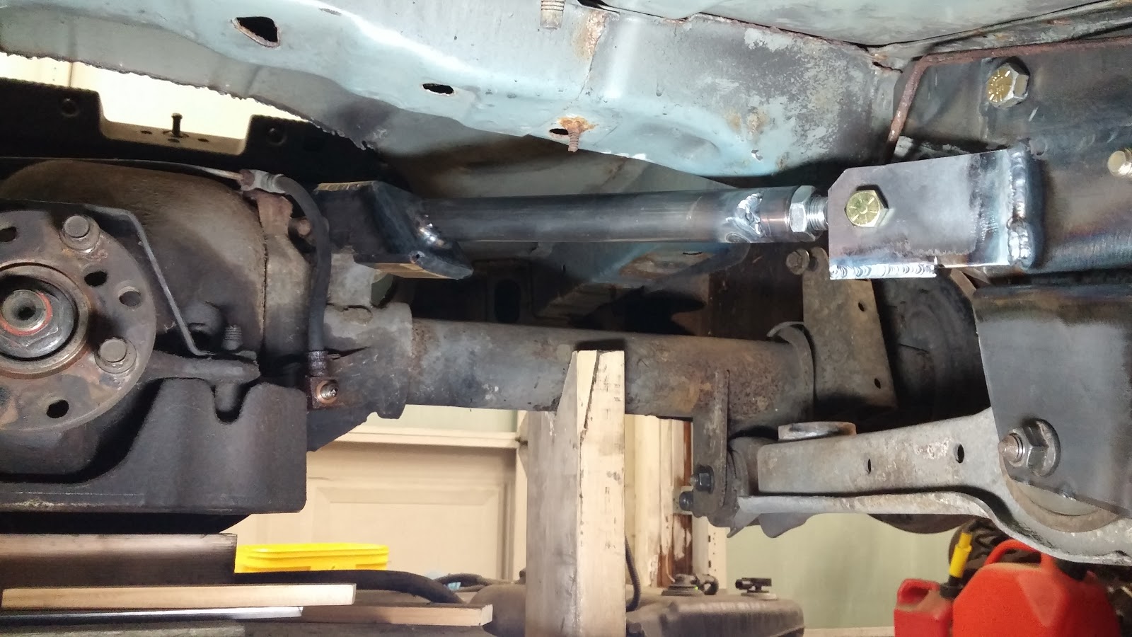
I finished the driver's side tonight so the 4 link is done and installed.  Here are the finished pictures forward looking aft.
Driver's side:
 Passengers side:


As soon as I was done I tried to shove the axle laterally.  It didn't budge and felt really solidly connected to the car.  Then I picked up the axle by the brake drum.  It came up easily with the other side still down heavy on the stand, which shows that there is no roll bind.  Next I went under the car and pulled out the shim that was holding the pinion at the angle I wanted.  It didn't move at all.  After removing the shim, I pulled down hard on the pinion and it didn't move at all.

I am super excited that this is working so well.  Everything is right where it is supposed to be.  The things that are supposed to move do, and the things that aren't don't.  Here are a couple pics from teh last couple days of fab on the driver's side:

Here is the second upper control arm clevis

Reused the positioning fixture:

Upper control arm tube weld:


First bracket piece tacked in place

 Welding on the upper mount.  Holding the torch upside down and clamping the hose to the sawhorse was the hot setup:


First part of the bracket welded on:

Here is the bracket with the upper control arm mount done

Beginning of the upper control arm tube adapter weld in.  I do this last so that I can bolt the clevis to the differential, and the the rod end into the upper bracket mount.  Then I can turn the loose tube adapter to extend or retract the rod end until  the length is perfect. Then I tack it to the tube and remove the control arm to weld fully.

I used mig for the rosette welds.  It works beautifully.  The uglier sides are where I fish mouth the tube.  Prepare to win recommends this as opposed to just welding all the way around as it puts some of the weld in shear instead of tension.  If nothing else it significantly increases the weld area.

Looking back I chose triangulated 4 link to avoid having to weld brackets to the axle housing which stressed me out.  I think now after all this fabrication I would feel pretty comfortable welding on an axle housing in the future.  Since I bought my welder I have used >3/4 of an 80 cubic foot argon tank with the flow rate on 20cf/hour.  So I may have as much as 3 hours of torch time.  It didn't seem like that much.  All that has been with steel, but wildly different positions, shapes, and thicknesses.  

From where I stand now, I still think triangulated 4 link was the way to go and am very happy to have reached this huge milestone.  This was the last of the really difficult things to do (aside from the headers).  I feel like this is definitely going to happen now, and feel more comfortable with the inevitable endless check writing that is needed to do the fuel system.


Friday, February 26, 2016

driver's side lower control arm bracket

Finished lining things up, rechecked the axle position, and welded on the inboard side of the lower control arm bracket last night: