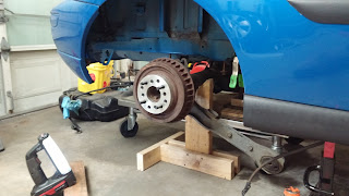
I am working towards connecting the control arms to the new frame rail brackets. I connected the sway bar so that the tow in on the control arms is set, and tightened down their pivots:
In theory I have to position the axle in 6 degrees of freedom:
3 translation
forward/aft
Left/right
up/down
3 rotation
pitch
roll
yaw
In practice though when I set forward/aft on each side I have covered yaw
When I set up / down on each side I have set roll.
I previously made a jig to set up down and set the axle at ride height so that is covered.
To set left right, I used the distance to the shock tower supports:
To set forward/aft I lined the axle up to be straight below the shock tower, which is the same location as stock:
This just leaves pitch. There is a lot of misinformation about setting the pitch angle. Bottom line is that the pinion angle needs to be parallel to (but not needed to be colinear with) the transmission tail shaft in order to prevent vibration. So if my tail shaft is pitched down 3°, then the pinion should be up 3°. Some may rationalize that it should be slightly less than this since the reaction of the axle under acceleration is to pitch upwards. This seems fine too, especially if you expect to be under high acceleration all the time.
Next step is to set the control arm angle. See figure below:
Figure: Lt blue lines are upper control arms. Red lines are the lower control arms. If we find the points that they would intersect, A and B, then the dotted line represents the roll axis. If that line is down hill as shown then the car will have roll understeer.
So if the lower control arms are pointed in fairly sharply, then they can point upwards a bit since point A is not that high. If the lowers are parallel, then Point A is at infinity, and any upwards angle to the lowers will cause roll oversteer. I measured the angle they form and it was about 10.5° from the centerline. This places their intersection point about 8.5 feet forward of the rear axle which is near the front wheels. I decided that even slightly uphill would lead to roll oversteer since that distance is so far away.
If I assume they are mounted level and look at how much suspension droop is needed before roll oversteer happens it is somewhere just before full droop travel. So I think I am good with level mounting. This will get me no antisquat to the geometry. Everything is a tradeoff. If I don't like how it turns out, it is a simple procedure to cut off the bracket clevis tabs and put new ones on. Tht is the upside of making them myself.
When I got the axle aligned and put the lower arms in place they were inboard to the point that they won't attach to my new bracket as is:
In other builds I looked at they fit. I am expecting either people used the SN95 axle which is wider, they use rod ends which are narrower and allow changing the angle relative to centerline, or they just force these outwards. I don't want to force them as it will wear out bushings faster, potentially cause some roll bind, and likely uncenter my axle, so I am going to build onto the brackets a little. I am putting together an order for this material, and the material for the custom upper control arms. This is getting long so I will cut this off here.


No comments:
Post a Comment