Sunday, December 4, 2016

parking brake complete


 Below is the worms eye view of the layout for the parking brake cable change I am making.  Left is the focus setup.  Right is the mustang setup.  The main difference is where the cable sheath goes (shown in green).  On the focus it starts from a bracket near the parking brake lever, and it ends at some point near the drum housing.
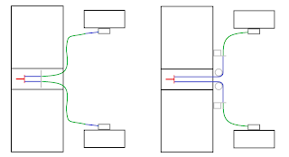
worms eye view.  Blue is the cable.  Green is the cable sheath.  Red is the cable bit attached to the handbrake.  Left diagram: Focus cable layout. Right diagram: mustang cable layout.
There were 3 problems with the focus cable:
1) The spring on the cable that retracts the parking brake shoe was too short.
2) The clip that holds the cable into the drum housing was flimsy brittle plastic, and the hole was slightly bigger on the drum which put more stress on this plastic.
3) Since the sheath ends before the drum, I would have had to weld up some large bracket to the control arm to receive it

The image on the right shows the mustang cable.  Here the cable goes all the way into the drum housing, so it instantly solves 1,2, and 3.  However, some fab was needed to put the mustang pulleys, and a new sheath termination bracket.

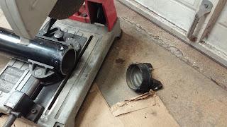
First I had to cut off the old focus parking brake bracket.  This is exactly what the plasma cutter is for:

When I started laying this out, I found that one mustang cable was frozen into the housing, and I couldn't get it to free up so I had to get another from summit before I could continue.  Below is the final routing tacked in. 


Here is the rest of the cable routing to the brake drum housing.  I zip tied the housing to the control arm at least for now to make sure it stays off the tire.


Monday, November 28, 2016

rear brakes

The rear brake lines from my old focus were so rotten that they came apart in my hand.  I bent up some new ones.  My bend tool makes the same diameter that ford uses.  I figured out that if I put in the old line I can mark where the bend begins, then transfer the mark.  


Drivers side brake line and hose:


 Passenger side brake and hose:
I am happy with how that all turned out.  I think it looks more or less factory.

I thought about transferring the spring on the parking brake cable to the focus cables.  But it just seemed like the wrong move.  I was worried that the focus cable wouldn't stay clipped into the drum (it is slightly smaller diameter than the mustang cable.  I was going to have to weld some large weird brackets to the control arms to hold the cable sheath ends, and that would still point the cables at a weird angle.

I layed out the mustang cable and figured out that it is the right length.  So I signed up for some fabricating.  More on that soon.


Monday, November 14, 2016

rear brake hoses and preliminary ebrake


I got an extra set of Focus front brake hoses and used them to finish the rear brake hose connections:
After I welded on the tabs I sprayed them with galvanizing compound.

I want to have a functioning e brake whether inspection requires it or not.  I saved the ebrake cable from the mustang and some pulleys that went with it.  I was really hoping that the focus ebrake cable would work since it is unlikely that I would be able to lay out the mustang cable without significant fabrication and/or luck.

It does look like it the focus brake will work:


Although the Focus end is smaller, it does fit into the ebrake arm in the mustang drum.  The spring is shorter which may cause trouble since the spring is what retracts the brake shoes when you release the brake. I may try to put the mustang spring on this cable, or make a collar or something.  I also need to make a mount to hold the end of the cable sheath.


Monday, October 31, 2016

rear brakes layout

Solid axle cars I have seen use hard lines on the axle with a single hose attaching in the middle.  My axle was set up this way, but the hard lines in the car had a hose at each wheel.  I decided to go with a hose directly to each wheel.  In retrospect it may have been simpler to tee the hard lines in the car together then connected them to the axle at the single point.

Ford has a clever way of doing brake hoses where the hose indexed into its mount with a small tab so it won't rotate:

I was hoping to preserve both this feature and preserve the mounting point for the hose to avoid the extra work I had to do for the front brakes.  I need brake hoses long enough that when I jack up the car I don't hang the axle from the hoses, but not so long that they have enough free movement to touch the tire.
Dorman's website allows me to search hoses by many different criteria.  I don't think three are any hoses with the Ford end that are female - female and long enough to reach.  The front of the car uses a long enough hose that is female - male.  To see if I could make the front hose work I tapped a piece of 11 gage sheet as a braket and there is enough room to thread the hose into it, then thread on a union. It looks about perfect:
The piece in the image and shown below is a bit of hard line I made to connect to the drum brake.  The left end is double flare and connects to the drum brake.  They right end is bubble flare and mates with the hose/union.


Thursday, October 27, 2016

driveshaft weld up

It is nice if I think I lathed the end straight, and also nice that I think I cut the shaft tube straight, but I decided driveshaft runout is probably the only thing that counts, so I decided to check it before I tacked it up, and I am glad I did.  There was about.080 TIM.  I looked online and it seems like people think somewhere from .005 to .020 is ok.  People report stuff like .060 being good to 80 mph, sometimes. The transmission end of the shaft measured at .020 so I made that my target.

I marked what was high and low, pulled the shaft out and tried to beat the cap straighter.  Put it back in, and checked it.  After repeating this process 3 or 4 times I was below .020 so I tacked it:


 I made this rig so I could in theory roll the tube while I welded.

It was easy enough to start and stop on the tacks so I didn't need to roll it.  I dipped the tungsten 0 times which was nice.  I could have slid along at like 85 amps and made this beautiful, but the bevel was pretty tight, so I had to really watch to make sure the puddle was wetting all the way to the bottom before jamming rod in.  Consequently I had to bake this a little bit especially with the heavy casting on the other side.  I went at like 110 amps and even that was probably a bit low as I was floored and waiting most of the time.  But it looks pretty good I think:


Monday, October 24, 2016

drive shaft shortening

I installed the slip yoke on the end that already has the right size u joint.


Next I have to liberate the end of the shaft so that I can weld it on later.

by the way, the tubing is .095 wall which was heavier than I expected.  Next I need to separate the steel tube from the casting.
I assume that the shoulder under the trunion is parallel to the u joint axis so I lined the part up based on that:

Then I machined through the weld.  You can see the rust peaking through right as I started to get through the tube and expose the casting:
Ready to weld with a beveled edge:
My u joint came from Amazon to convert from 1 3/16 to 1 1/16.  

Once I had all that together, I would see the distance from the beveled cut to the very end and see where to cut the tube.  I scored it with the cutting disk in the die grinder then finished the cut with the 4 1/2:

Then I heated the end of the tube up with a map gas torch and beat the u joint in.  I used a piece of angle to line up the Ujoints at each end.  I wasn't sure how close the had to be.  A co-worker told me .125° or there would be big trouble.  The internet doesn't seem to agree.  Seems like 5° is common, which I am more inclined to believe (maybe because I have to!)


Here is the end stuck in the transmission.  Pretty much right where it used to be on the yoke:


Here is the end into the pinion.  Looks good.  Not a lot of clearance on the e brake cable

Just need to weld it up


Wednesday, October 19, 2016

drive shaft planning

Finished painting and welding in the drivers side suspension mounts and control arms.  Since I can't tighten the through bolts super tight (would crush the frame rails) I tacked the nuts and bolt heads down with a spot weld to help hold everything still (locktight is for pansies!).  These bolts are permanent, but if I ever want them out, I put the tack in an easy to cut spot.

I decided to tackle the driveshaft next.  I put the mustang drive shaft up under there and wouldn't you know I need a longer driveshaft, not shorter.  After contemplating combing a junkyard for a manual shift pickup with an 8 foot bed, I decided to just have one made.  I asked my buddy Kenny where he had his made, and he had one laying around and several different size u-joints he said I could have.

Rusty one is from the mustang.  Black one is from Kenny's truck before he went to a two piece driveshaft to fix some vibration issues:


So yes this thing vibrates above about 80 mph.  Shortening it by 20% should cure that, so if I have vibration issues, I will get it balanced and I expect that will be the end of that.  Also, It is fun to think of my car as powerful, but it is nothing compared to kenny's truck so it should be fine.  

The U joint on one end was the right size.  The one on the other end and the two new ones that he gave me are all not the right size.  Drive shaft pivot was 1 3/16 dia, and the bit attaching to the pinion was 1 1/16 dia.  Found a spicer u joint that hits both of those (5-648x) for $30 on Amazon.  So I grabbed some brake hoses to hook up the rear brakes.

Went ahead and removed the u joint from the end of the shaft.  It is nice to have a press for this.  So much more civilized than trying to beat it out of there.


Sunday, October 9, 2016

PS rear suspension finish up

Since I finished fabricating the rear suspension and everything fits, I took apart the passenger side this weekend and finalized things.

I welded patches over the holes that were for the shock mounts and painted the suspension cross bar:
I had this bar hanging from a tree to paint it.  My daughter decided that she wanted to climb the tree.  As soon as I was walking away from this after the first coat of paint, she pulled it down and threw it in the mud.  Who would have guessed there was a gene for being unwilling to tolerate my nonsense...

Painted the upper control arm:


Primed the bracket.  For the inside of the bracket, which will contact the frame rail, I painted it with galvanizing compound.  For the edges where I expect to weld I used weld through primer.  Everywhere else I used standard primer:

Although I used three large bolts to hold this in,  I didn't want any movement and wanted to give this assembly a little help, so I welded it also especially since this is one of those things that isn't allowed to break.  

I haven't used GMAW lately especially downhill or overhead, so I spent a few minutes on Weldingtipsandtricks.com before I got started. Jody Collier's videos are by far the best ones I have found online.  His arc shots really help me to see how things should look, and I especially appreciate that he explains why things are the way they are.
Weld close ups:


I think that spending the last year focused on tig welding has helped my mig welding.

Here it is with everything back in there:


Wednesday, August 31, 2016

Worthwhile diversion

I am trying to limit the scope of this blog to just the focus build and eliminate exciting excuses like, I went on vacation here

and that is why I haven't been around. 

In addition to being out for a while, I have been shopping for a truck for a while.  Most trucks live a hard life then when they 95% ruined people dump them on CL.  After searching a while, I found one that was in fantastic condition, except the engine blew up.  I spent the last couple weeks on weekends and after work putting in a new motor.

On the day it was time to start it up I was cranking it with the plugs out and injectors off to get oil pressure and it was not happening.  My friend Seth pointed out that some oil pumps won't start to pump without a prime.  I thought about how to get oil into an already installed and closed up engine, and came up with this way:
I drilled two holes in the cap of a quart of oil.  In one hole I put a piece of small tubing.  I removed the truck oil filter and jammed the other end as far in the oil filter manifold oil inlet as far as it would go (I got about 4 to 6 inches in).  Through the second smaller hole, I slid a needle attached to a bike pump.  When I pumped air into the bottle, it pumped oil into the oil pump.  After doing this.  I cranked the car for about 7 more seconds with no filter on, and oil came flying out (I drink your milkshake!)  Then put the filter back on and saw oil pressure in about 4 more seconds of cranking.

At the beginning of start up day, it was such a pain in the butt to get the pressure gage hooked onto the engine, and I was tempted to just start the car, and give it 5 seconds to clear the low pressure idiot light that I presume would have been lit.  After all, how often does an engine not get oil pressure?  Maybe the higher pump speed would have made it suck oil, but I am sure glad I took the time to do this right.

Monday, July 11, 2016

rear springs part 3

Choosing spring rate will control how how much travel is available in droop before the spring is unweighted.  It will also be related to how easily the car bottoms out.  Especially since inclined springs mean that I have a falling rate suspension.  The shocks that I have give three numbers, fully compressed length, fully extended length, and ride height.
For my shocks ALN5855P we have:

Extended height: 16.375 inches
Compressed height: 11.125 inches
ride height: 13.5 - 14 inches

Since coil overs are adjustable, I can moved the collars up or down to put the shock length in the ride height range regardless of the spring rate I choose.  However, suppose I choose a spring that is way too stiff. So that the spring only compresses .5 inches when I put the car onto its wheels.  If I put the ride height where recommended (14 inches), then we run out of load on the wheel at 14.5 inches extension.

Ideally, I want the wheels to become unweighted at full extension of the shock.  I previously measured the unsprung weight of the car at a surprising 330lbf or (165lbf per side) so a spring that sags 2.375 inches from 165 lbf would be 70 lbf /inch.  Since I have a 14° installation angle that becomes about 80 lbf / in.

That seems really low.  I have concerns that changing fuel load or passengers will significantly change ride height, and that the heavy axle when moving upwards in bump will be too likely to reach the bump stops in street driving.  I bumped the rate up to 150 lbf / inch.  Interesting to note that if you buy the cheap summit springs, you can see that it has QA1's logo faintly through the finish...

I finished the mount and put the springs and shocks in.  Here is a shot from the back.  I think this flies under the radar nicely.

I got in the trunk and jumped up and down.  The suspension moved freely about the same magnitude as any passenger car would.  Encouraging.  A few things were rubbing / not lined up how I wanted, so I will take a couple days to adjust some things, remove and paint all the rear suspension bits and attach them permanently.

Tuesday, July 5, 2016

Hey, kids it's me! I bet you thought that I was dead!

I have actually been working, just not posting.  I expected to do the rear spring mounts really quick and then just post it all when it was done.  It turned into an epic and still isn't done, but close.


I had to drill out this slot to .5 inch.  It grabs a drill bit the instant it touches it. Sooo

Welded a cover over the hole...

Drilled the hole...

Then cut off the cover.  Bolt on this bracket:
 Make the other side:


weld on a standoff:

For where the shock mounts to the car, I had to move the mounts up quite a bit from the bar I made back in part 1.

Figure it out with cut up cards.  From the calculations (I will post these shortly) we see that as the springs depart from vertical orientation we get a falling rate suspension.  In other words the more the spring compresses, the lower the wheel rate becomes.  You want wheel rate constant or at least rising, so that there is nice compliant ride at small displacement, and then becomes stiffer as the spring deflects to help prevent hitting the suspension bump stops.

If I mount the springs vertical and near the differential like they do on drag cars, then I have a suspension that for a given bump stiffness is not stiff in roll.  So I am aiming to have the shocks as close to vertical and as wide as I can. I also have to setup in the range the manufacturer lists for ride height for the shock.  And pick the springs that will support this ride height.
Lay it out (handy to have the plasma cutter here to let me nest these close)

Had to awkwardly tig tack these since the mig won't reach. 
Right hand holds the torch
Left hand jams the filler
Other left hand holds the parts

 I am further than this, but don't have enough pictures to show the story.  Will post again later...